A boiler tube experienced a burst. The failed tube was analyzed using metallographic microscopy, direct-reading spectroscopy, and scanning electron microscopy. The analysis revealed that the steel pipe underwent hydrogen-induced corrosion under high temperature and pressure, leading to the formation of extensive grain boundary cracks on the inner wall. At the same time, an oxidation reaction occurred, resulting in the development of a thick oxide scale layer. When the furnace is shut down or subjected to significant load fluctuations, the oxide scale layer on the tube wall may detach and accumulate in certain areas, obstructing water flow. This blockage causes a rapid temperature rise, leading to overheating and eventual tube failure.
The heating tubes in industrial boilers comprise several pipes and are critical to the boiler's operation. Water or a water-vapor mixture flows through the tubes, while heat from sources such as flue gas and thermal radiation is transferred to the fluid via convection. Boiler tubes operate under high temperatures and pressures for prolonged periods, and their failure mechanisms include prolonged and transient overheating, wear, oxygen corrosion on the flue gas side, stress corrosion cracking, thermal fatigue, high-temperature corrosion, and material quality issues. The 20G steel pipe is widely used for boiler tubes due to its low carbon content, high plasticity and toughness, as well as excellent formability at both low and high temperatures and strong weldability. Research into the failure analysis and prevention of these pipes remains a key focus.
The failure occurred in a 20G steel pipe with an approximate diameter of 62 mm in a factory boiler’s furnace. The pipe had been in service for 4 years before the failure. The boiler was overhauled 20 days prior to restarting the furnace. The pressure was within normal operating range before the furnace was reignited. Three days after restarting the furnace, multiple tubes failed, all on the fire side of the pipes. Two distinct failure modes were observed: one exhibited a trumpet-shaped opening with significant crack expansion, while the other showed minimal expansion, resembling bark-like fractures. The latter failure mode was more common, and some cracks did not penetrate the pipe wall. Prior to failure, the external flue gas temperature was approximately 900°C, the internal temperature was around 270°C, and the pressure was 5.0MPa.
Two sections of the failed
boiler tube were labeled as Section 1 and Section 2.
Section 1:
The section of the pipe had a diameter of 61.5 mm. At the burst location, the diameter was enlarged to 67.7 mm. The pipe wall thickness varied, with the thickest point measuring 5.2 mm and the thinnest point 2.4 mm. The crack at the burst site ran longitudinally in a trumpet shape, measuring 33.6 mm in length and up to 7.8 mm in width. The pipe wall at the burst site tapered to a blade-like shape, with a thickness of approximately 0.64 mm. The oxide scale on the outer surface of the thinned region showed distinct longitudinal cracks. The inner wall at the burst site was dark red with a prominent oxide layer. The macroscopic morphology of the burst site is shown in Figure 1(a).
Section 2:
The section of the pipe had a diameter of 62 mm. The inner surface facing the fire was extensively oxidized, with a brownish-red oxide layer. Upon removal of the oxide layer, numerous corrosion pits were observed, with the scale thickness ranging from 0.5 to 1.8 mm. The outer surface of the fire-facing side was also significantly oxidized, with numerous cracks running parallel to the pipe's axis. The edges of these cracks were blunt, resembling bark-like fractures (B-4 morphology). The macroscopic morphology is shown in Figures 1(b) and 1(c).

(a) Macro-morphology of the 1” pipe section
(b) Macro-morphology of the outer wall of the 2” pipe section
(c) Macro-morphology of the inner wall of the 2” pipe section
Figure 1 Macro-morphology of the failed pipe
Chemical composition analysis of the oxide scale layers removed from the inner walls of two pipe sections and the 2-inch pipe section was performed using a direct-reading spectrometer. The elemental composition of the tested pipe sections complied with the chemical composition standards for 20G steel pipes as specified by GB 5310-2008 (see Table 1). Wet chemical analysis of the oxide scale from the inner wall of the 2-inch pipe section identified the primary components as iron oxide (Fe₂O₃/Fe₃O₄), calcium oxide (CaO), and magnesium oxide (MgO). The results are shown in Table 2.
Table 1 Failed Pipe Composition Test Results
| Element Composition |
C |
Si |
Mn |
P |
S |
| 1" Pipe Section |
0.18 |
0.22 |
0.54 |
0.015 |
0.013 |
| 2" Pipe Section |
0.18 |
0.22 |
0.52 |
0.016 |
0.006 |
Table 2 Chemical Composition of Oxidation Scale
| Chemical Composition |
Fe₂O₃/Fe₃O₄ |
CaO |
MgO |
| Oxidation Scale Peeling from the Inner Wall of the 2-inch Pipe |
86.39% |
0.87% |
0.29% |
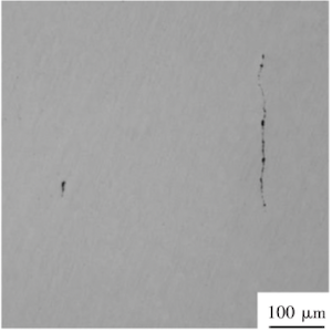
The analysis of non-metallic inclusions in the failed tube revealed a high concentration of silicate inclusions distributed across multiple fields of view. These inclusions were primarily continuous, with the longest measuring approximately 300 µm, as shown in Figure 2. Non-metallic inclusions disrupt the matrix continuity, initiating and propagating cracks. As the matrix corrodes, areas where the inclusions bond with the matrix are more susceptible to corrosion, resulting in partial corrosion at the inclusion-matrix interface. This corrosion spreads, causing pitting that reduces mechanical properties and increases fracture susceptibility.

Figure 2 Non-metallic inclusions
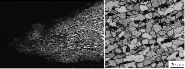
Figure 3(a) shows the fracture surface morphology in the 1-inch pipe section. The pipe wall edge is significantly thinned, and the microstructure shows elongation and deformation along the direction of the fracture. The microstructure near the fracture consists of ferrite and pearlite, with the pearlite clearly spheroidized. According to DL/T 674-1999, "Grading Standard for Spheroidization of Pearlite in No. 20 Steel for Thermal Power Plants," the spheroidization level is between 4 and 5, with carbides precipitating at the grain boundaries (see Figure 3(b)).

(a) Morphology and structure of the breach edge (b) Microstructure near the breach
Figure 3 Breach morphology of the 1" pipe section
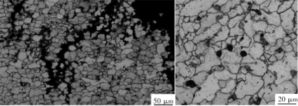
The 2-inch pipe section shows multiple cracks exhibiting a mesh-like distribution along the pipe wall. The primary crack consists of fine fissures that extend along the pipe, displaying typical corrosion crack morphology (see Figure 4(a)). The presence of these fine fissures disrupts the bond between grains, reducing the material's strength and ductility. Under external stress, brittle fracture is more likely to occur. Examination of the microstructure at the crack revealed high-temperature oxidation and decarburization, with pearlite virtually absent. The microstructure was primarily ferrite grains, as shown in Figure 4(a). At the center of the tube wall, pearlite remained but underwent significant spheroidization, with some spheroidal graphite present. The spheroidization reached level 5, as shown in Figure 4(b). Based on the microstructural analysis, the 2-inch pipe section shows signs of hydrogen corrosion and prolonged overheating.

(a) Crack microstructure (b) Microstructure at the center of the pipe wall
Figure 4 Microstructure of the 2" pipe section
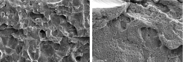
SEM analysis of the crack in the bark-like area of the 2-inch pipe section revealed a smooth fracture surface morphology with numerous corrosion pits, as shown in Figure 5(a). The fracture exhibited typical brittle fracture characteristics, displaying a rock candy appearance along the pipe, as shown in Figure 5(b).

(a) SEM image of corrosion pit
(b) SEM image of crack fracture
Figure 5 SEM image of 2-inch pipe burst
- According to GB 5310-2008, the chemical composition of the failed pipe section complies with the standard requirements for 20G steel.
- Macroscopic analysis, scale layer examination, metallographic analysis, and SEM fracture analysis of the fracture site in the 1-inch pipe section reveal a trumpet-shaped rupture, with a marked increase in pipe diameter. The pipe wall gradually thins, forming a knife-edge appearance. The fracture shows typical signs of ductile failure, accompanied by rapid cracking due to high temperature.
- In the microstructure at the fracture site, pearlite is severely spheroidized, and fine strain markings are visible on the pipe wall due to plastic deformation. The microstructure is elongated along the direction of deformation, indicating that the fracture site was subjected to overheating near the phase transition temperature (Ac) for a brief period. This caused a significant reduction in pipe wall strength. Under internal pressure, circumferential tensile stresses cause the pipe diameter to gradually expand and the wall to thin. When the pipe wall thickness falls below its strength threshold, rupture occurs.
- Macroscopic analysis, scale layer examination, metallographic analysis, and SEM fracture analysis of the 2-inch pipe section reveal that the inner wall is covered by a thick oxide scale layer with corrosion pits. The pipe wall has undergone significant decarburization, and numerous intergranular cracks extend from the inner surface through the wall thickness, exhibiting typical signs of prolonged overheating and hydrogen corrosion.
- Extended exposure to high temperatures and hydrogen corrosion leads to decarburization of the pipe wall surface, forming an iron oxide scale that thins the pipe wall. Moreover, the scale layer significantly impairs the heat transfer efficiency of the boiler. When the scale adheres to the tube wall, 1 mm of scale can increase the tube's effective thickness by several millimeters, significantly raising the thermal resistance. As the scale thickens, it obstructs water flow and impedes cooling of the tube wall, leading to prolonged overheating and a steady reduction in the tensile strength of the steel tube. As the tube wall temperature increases, the microstructure undergoes extensive spheroidization, and spheroidal graphite forms. Prolonged overheating leads to the formation of axial cracks in the boiler tube.
- The failed tube contains a high concentration of Class C non-metallic inclusions, widely distributed throughout the material. These inclusions promote pitting corrosion and crack propagation, reducing the service life of the pipe fittings and accelerating boiler tube failure.
In conclusion, the failure of the steel tube was caused by two distinct mechanisms. The first mechanism is short-term high-temperature failure, where oxidation due to elevated temperatures leads to the formation of a thick oxide scale layer. When the furnace shuts down or experiences significant load fluctuations, the oxide scale layer may detach and accumulate in specific areas, obstructing water flow and causing blockages. This results in partial overheating, a rapid rise in temperature, and ultimately tube rupture — the primary failure mechanism.
The second failure mechanism involves long-term overheating and hydrogen corrosion, which causes axial cracks in the pipeline, leading to failure. Hydrogen corrosion results from the presence of hydrogen beneath the scale, which hinders outward diffusion and leads to material degradation. As hydrogen corrosion progresses, the steel pipe wall deteriorates, which leads to the formation of numerous grain boundary cracks. Extended exposure to high temperatures and hydrogen corrosion causes severe decarburization of the microstructure, significantly reducing the steel pipe's service life.
Analysis of the cracked pipe fittings indicates that the service life of these boiler tubes is limited. Although most corrosion pits and cracks do not penetrate the full wall thickness, some cracks extend through the wall, resulting in water seepage. This represents the secondary failure mechanism.


