Pipeline pigging operations are gaining increasing attention. Various technical problems may arise during the pipeline pigging process. During the pre-inspection pigging of a natural gas pipeline, it was discovered that the foam pigging was damaged for unknown reasons. After further diameter measurement pigging, arc damage marks were found on the end face of the straight leather cup. After analyzing the arc damage marks, the characteristics of miter joints, tees, and pressure openings were ruled out, and it was determined that the cause of the pigging damage was an incompletely opened valve. Based on the second diameter measurement pigging sent and the posture comparison of the two pigs in the ball receiving barrel, it was determined that the faulty valve was the first valve before entering the station. After maintenance, the pigging was sent again, found to be in good condition, and the valve fault was resolved. The hazards were eliminated, and the pigging work was successfully completed.
Pigging uses the pipeline transportation medium as a power source and employs pigs with various structural forms to remove impurities from oil pipes, improving transportation efficiency and cleanliness. Pipeline cleaning has always been an indispensable process in pipeline systems. The concept of pipeline integrity management is gaining increasing popularity in the pipeline industry. As a crucial aspect, pipeline pigging operations are receiving increased attention. Before internal pipeline inspections, pigging is typically required to meet the internal detector’s standards for pipeline condition. In previous pipeline pigging operations, engineers and technical personnel have studied issues such as pig blockages, leakage ball stops, and pig structure. This paper analyzes the causes of pig damage encountered during the pigging process of a natural gas pipeline.
The basic specifications of the pipeline are as follows: natural gas is the transportation medium. The pipeline diameter is 508mm; the length is 67km, and the operating pressure is 2.5MPa. There are 9 cut-off valves in the main pipeline, all of which are ball valves. There are two equal-diameter tees in the pipeline. To ensure a smooth internal inspection, pigging is scheduled beforehand. The prepared pigs include foam pigs, diameter-measuring pigs, steel brush pigs, and magnetic pigs. After switching the process, the foam pigs were launched, and the pigging process proceeded smoothly. After the foam pig was collected by the ball collecting tube, damage was discovered in the middle of the pig. The damage is shown in Figure 1. The shape of the damaged area suggests a tear caused by a rigid object cutting into it, with a width of 410mm and a maximum depth of approximately 50mm. The cause of the damage cannot be determined based solely on the current condition, and further investigation is required. After evaluation and analysis, the diameter-measuring pig can be deployed under the current pipeline conditions.
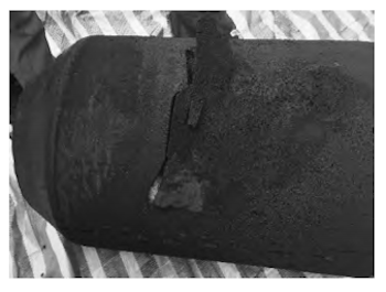
Figure 1 Damaged parts of the foam pipe piggingging
The structure of the diameter-measuring pigging consists of two straight leather cups and three disc leather cups, with the diameter of the measuring plate being 443mm (Figure 2). After the diameter-measuring pig completes the ball collection, the leather cups exhibit normal wear, the measuring plate shows slight deformation, and a deep arc-shaped indentation is observed on the end face of the front straight leather cup (Figure 3), forming an incomplete crescent shape with the outer contour of the cup. The depth of the indentation is mostly uniform, with the maximum distance from the edge of the straight leather cup being 57mm.
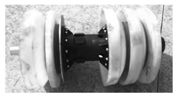
Figure 2 Pipeline pigging
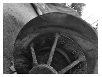
Figure 3 Indentation on the end face of the straight leather cup at the front end of the pipe piggingging
Based on the damage patterns, trace marks, and size consistency of the two pigs, it is believed that the same feature caused the damage. The regular shape of this feature likely corresponds to some abnormal pipeline accessory. Considering the pipeline conditions, the possible scenarios matching this regular shape are listed in Table 1. If it is a large-angle bevel connection, it may damage the foam pig but will not affect the other pig. If the tee baffle falls off and causes the pig to partially enter the tee, the side edge of the leather cup will first contact the pipe wall and bear the force. In this case, the two ends of the crescent-shaped trace on the pig should be deeper, with the middle being shallower (Figure 4). If the damage is caused by misalignment and warping of the saddle plate with a pressure opening, the front end of the saddle plate will first contact the middle of the leather cup, causing the arc-shaped trace to be deeper in the middle and shallower on both sides (Figure 5).
Table 1 Statistics of possible situations of different pipeline parts
| No. |
Feature |
Foam Pipe Cleaner |
Size Measuring Pipe Cleaner |
| 1 |
Mitered joint |
Possible |
Impossible |
| 2 |
Tee retaining bar falling off |
Possible |
Possible |
| 3 |
Saddle plate with pressure opening dislocated and lifted |
Possible |
Possible |
| 4 |
Valve not fully opened |
Possible |
Possible |
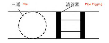
Figure 4 The pipe piggingging passing through the tee
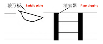
Figure 5 Tilted saddle plate pressure opening
If the valve is not fully opened, the valve core of the ball valve will be at an angle to the pipeline axis (Figure 6). Since the front end of the foam pig has a guide angle and strong deformation ability, it can easily enter the valve core without leaving any traces (Figure 7). As the foam pig moves further into the valve core, the contact force between the middle of the pig and the valve core increases, reaching a maximum and causing the foam to be cut. The foam pig continues to move forward under pressure, and the force at the incision gradually decreases. The incision will stop increasing and remain unchanged until the pig passes through.
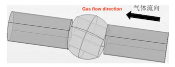
Figure 6 Three-dimensional diagram of valve not fully open
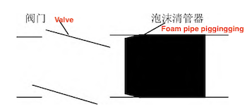
Figure 7 Valve not fully open (foam pipe piggingging)
Since the front end of the diameter measuring pig is a straight leather cup without a guide angle, the first contact point between the valve core and the leather cup is the end face of the leather cup (Figure 8). The pig will remain under pressure here until the thrust generated by the pressure difference exceeds the resistance caused by the deformation of the leather cup, allowing the pig to quickly pass through the valve core. Since the angle between the valve core and the pipeline is generally small, the projection of the valve core edge along the pipeline is approximately a straight line, so the marks created by the contact with the leather cup’s end face are uniform in depth. This is consistent with the actual behavior of the pig.
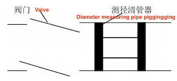
Figure 8 Valve not fully open (diameter measuring pipe piggingging)
Based on this conclusion, further careful observation of the diameter-measuring pig revealed two phenomena: (1) An arc-shaped indentation was observed near the steel flange of the pig on the end face of the straight leather cup, with scratches radiating outward (Figure 9). (2) An arc-shaped deformation was found on the rear diameter-measuring plate, opposite the crescent mark on the front leather cup. These two situations occur because, as the pig is about to leave the valve core, the front end of the leather cup strikes the edge of the valve seat a second time. When the diameter-measuring plate is about to exit the valve core, the pig tends to return to its correct position from its deflected state, causing the opposite side of the diameter-measuring plate to collide with the valve core and deform.
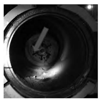
Figure 9 Secondary scratches on the end surface of the straight leather cup
After analysis, it can be determined that the cause of the pipe pigging damage is a valve on the pipeline that is not fully opened. However, there are nine valves along the pipeline, and it is impossible to determine which one is not fully opened. Therefore, it was decided to send a diameter-measuring pig again to monitor each valve along the line and make a preliminary judgment based on the time the pig spends at each valve.
After sending the diameter-measuring pig for the second time, it remained stationary before and after the first valve before entering the station. This indicates that there is a problem with this valve. Simultaneously, when comparing the status of the two diameter-measuring pigs in the ball barrel (Figures 10 and 11), it was found that the arc marks on the end faces of the two leather cups appeared between 3 o'clock and 4 o'clock (from the rear end to the front end of the pig). The distance between the ball barrel and the valve is less than 10 meters, indicating that the pig can be considered non-rotating within this short distance. Therefore, it is concluded that the clock position of the arc mark under pressure is at 3 o'clock. This is also consistent with the conventional position of the valve when it is not fully open. Furthermore, the orientations indicated by the two diameter-measuring pigs are consistent, further confirming the inference.
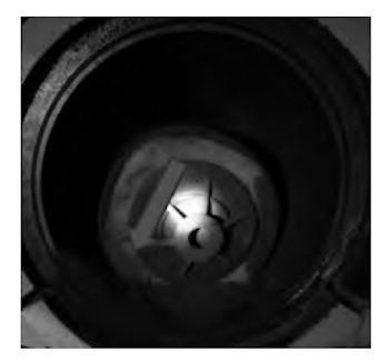
Figure 10 Status of the first diameter measuring pigging in the ball barrel
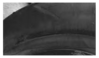
Figure 11 Status of the second diameter measuring pigging in the ball barrel
After disassembling the valve stem mechanism of the identified valve, it was found that the damage was caused by the misalignment of the limit and indication mechanisms. After adjustment, the indication was restored to normal, and the next round of cleaning was conducted. The pig did not remain at the valve. After the ball was collected, no arc marks were observed on the leather cup of the pig. This confirms the correctness of the analysis.
Through detailed analysis and inference of the faults found during the cleaning process, the valve failure was eliminated, along with the risk of equipment impacting the blind plate due to pressure holding during the subsequent ball passing process; the damage to downstream equipment caused by violent pressure fluctuations was avoided, thereby ensuring the gas safety of downstream users. In the future, extensive cleaning operations will encounter various technical problems, and it is necessary to resolve these issues to identify the root causes, eliminate risks and hidden dangers, and ensure the smooth completion of the cleaning process.


