Carbon steel pipes are widely used in submarine oil and gas exploration projects worldwide due to their proven design for pipeline installation. However, in environments with rugged seabeds and variable geological conditions, carbon steel pipes encounter major challenges. This paper analyzes these limitations, focusing on construction challenges, engineering costs, and operational and maintenance concerns, using domestic and international case studies. Additionally, it explores the advantages of hoses and offers recommendations for selecting optimal piping solutions in such environments.
Submarine pipeline installation is essential to offshore oil and gas development. Carbon steel pipes remain the primary choice due to their proven design and widespread use. However, as oil and gas exploration expands into deeper waters and increasingly complex geological conditions, the limitations of carbon steel pipes are becoming more apparent. This paper evaluates these limitations and examines the feasibility of hoses as a viable alternative.
In offshore oil and gas development, submarine pipeline routes are determined by the following design criteria:
- Cost efficiency: The route should be optimized to minimize engineering costs while ensuring construction feasibility and long-term operational and maintenance viability.
- Avoid crossings: Minimize intersections with existing pipelines whenever possible.
- Avoid obstacles: Steer clear of submarine hazards such as reefs and shipwrecks whenever possible.
- Stable seabed: Select a level, stable seabed to reduce pipeline overhangs.
- Special requirements: Adhere to project-specific requirements, such as maintaining a minimum 30° angle between new and existing pipelines or avoiding ecologically sensitive areas like coral reefs.
- Traditional carbon steel pipes meet these criteria in geologically stable offshore areas. However, in complex geological conditions, their application presents significant limitations, increasing construction challenges, raising engineering costs, and making maintenance more challenging.
In mature offshore developments, pipeline routing is often constrained by limited space and sharp curves, requiring pipelines to follow curved paths. Because of their high stiffness, carbon steel pipes require a larger bending radius for installation. The minimum bending radius of carbon steel pipes is determined by the following equation:

Where:
- H is the residual tension of the pipeline,
- μ is the lateral friction coefficient of the soil,
- Ws is the soil weight, and
- FR is the passive resistance of the soil.
In practice, the bending radius of carbon steel pipes often fails to accommodate complex routing requirements. For example, in an international project, the bending radius of carbon steel pipes did not align with the surveyed route. When carbon steel pipes must be used, the only way to navigate turns is by installing expansion bends. However, expansion bends increase both construction costs and the risk of leaks.
In contrast, because of their greater flexibility, hoses can accommodate turns with a significantly smaller bending radius. A standard 10-inch hose has a minimum bending radius of approximately 50 meters, making them suitable for most complex routing needs. Additionally, hoses eliminate the need for welding during installation, significantly reducing both construction time and costs.
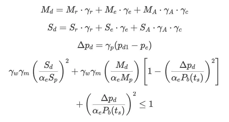
In offshore regions with dense pipelines, new pipelines often cross existing ones. Traditional steel pipe crossing methods involve placing support blocks on existing pipelines before installing new ones. Software simulations determine functional and environmental loads, which are then validated against DNV specifications:

Where:
- γA, γE, γF, γD are load effect factors,
- γC represents conditional load effect factors,
- γS, γM are safety level resistance factors and material resistance factors, respectively,
- Md, Mr, Me, MA denote design bending moment, functional load bending moment, environmental load bending moment, and accidental load bending moment, respectively,
- Sd, Sr, Se, SA indicate design effective axial force, functional load axial force, environmental load axial force, and accidental load axial force, respectively.
Software simulations optimize steel pipe crossing designs by strategically placing support piers between existing pipelines, improving load distribution across the crossing structure. Engineering analysis confirms that the pipeline meets strength requirements. However, steel pipe crossings are complex and costly.
In contrast, flexible pipes can use Uraduct for crossings. Uraduct allows installation directly from a pipe-laying vessel, which simplifies construction and reduces installation time. Additionally, it eliminates the need for on-site welding, further reducing construction costs and the risk of leaks.
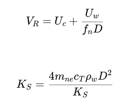
In seabed areas with a high density of obstacles, identifying an entirely unobstructed route is highly complex. Due to the inherent stiffness and strength limitations of carbon steel pipes, these materials often do not meet the required allowable span when faced with large obstacles. The maximum dynamic allowable span for a pipeline is calculated using descent velocity (VR) and the stability coefficient (KS), as defined by the following equation:

Where:
- Uc: Nominal flow velocity
- Uw: Intended wave velocity
- fn: Natural frequency of the pipeline span
- D: Outer diameter of the pipeline
- mn: Effective mass
- cT: Damping ratio
- ρw: Fluid density surrounding the pipeline
For a specific project, analysis using appropriate modeling software indicated that the maximum allowable span for an 8-inch carbon steel pipe was 13 meters, necessitating significant seabed preparation. In contrast, flexible piping systems require fewer seabed modifications, allowing standard seabed conditions to meet the necessary construction and operational requirements.
This paper analyzes the limitations of carbon steel pipes in complex geological conditions, drawing on both domestic and international engineering case studies. The key findings are summarized as follows:
- In projects involving shallow bends, intersections with existing pipelines or cables, or areas requiring seabed preparation, flexible piping systems offer distinct advantages over carbon steel pipes in terms of installation feasibility, maintenance, and project efficiency.
- Due to their flexibility and reduced construction requirements, flexible piping systems may provide an effective solution for submarine pipeline installation in challenging geological environments.
- During the material selection phase, the potential benefits of flexible piping systems should be thoroughly evaluated, especially for applications in complex geological conditions.


